The Complete Process of Industrial Interface Repair, Explained Step by Step
Industrial machines depend on interfaces to communicate commands, display data, and keep operations running smoothly. When these components fail, entire production lines can grind to a halt. Understanding the interface repair process is critical for plant managers, maintenance engineers, and facility operators who need to minimize downtime and restore operations quickly.
This guide walks through the complete, step-by-step process of interface repair from the first sign of a fault to final verification.
An Overview of Industrial Interface Systems
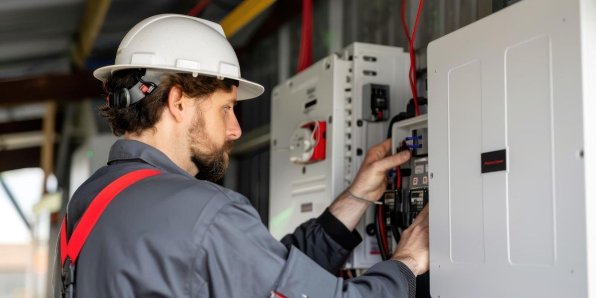
An industrial interface refers to the human-machine interface (HMI), operator panels, touchscreens, display units, and control terminals used in manufacturing, automation, oil and gas, power generation, and other heavy industries. These devices help connect the machine’s system with the operator’s commands. Since they are constantly used and exposed to heat, dust, and vibrations, they can wear out or face both hardware and software issues over time.
Step-by-Step Guide to the Industrial Electronics Repair Process
The industrial interface repair process is not the same as repairing consumer electronics. It requires specialized diagnostic tools, technical knowledge of industrial communication protocols, and access to compatible components, many of which are no longer in mass production.
Step 1: Fault Identification and Initial Assessment
The first step in any industrial electronics repair begins with thorough fault identification. Before any panel is opened or a component touched, the technician must gather as much information as possible about the failure.
This involves interviewing the machine operator to understand when the fault occurred, what the display showed before failure, and whether there were any unusual sounds, smells, or events leading up to the problem. Error codes, alarm logs, and event histories stored in the controller are reviewed at this stage.
Common interface faults include:
- Blank or flickering display screens
- Unresponsive touchscreens or keypads
- Corrupted graphics or frozen interfaces
- Communication errors with the PLC or SCADA system
- Power supply failures are causing intermittent shutdowns
A detailed fault report is created at this stage. This document guides every subsequent step in the interface repair and ensures nothing is missed.
Step 2: Visual Inspection and Physical Examination
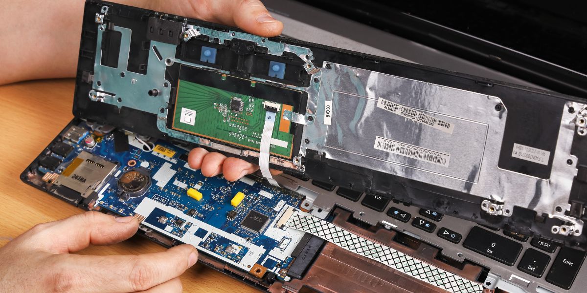
Once the unit is safely powered off, the next step is a careful visual check. This stage is simple but very important in the repair process.
Technicians look at the PCB (printed circuit board) for any visible damage like burnt parts, leaking capacitors, rusted connectors, broken tracks, or signs of moisture or chemical exposure. The display is also checked for issues such as cracks, backlight problems, or the touch not working.
They also inspect connectors and ribbon cables to make sure everything is properly connected and not damaged. Cooling fans and air vents are checked for dust or blockages that could have caused overheating. Often, this step helps quickly spot the problem, like a blown fuse, damaged capacitor, or burnt resistor, making it easier to plan the repair.
Step 3: Electrical Testing and Diagnostics
After the visual check, the next step is detailed electrical testing. Technicians use tools like multimeters, oscilloscopes, and other testing equipment to check how each part of the unit is working. They make sure the right voltage is reaching important components like the display, processor, and memory.
Signals are also tested to confirm smooth communication between parts, including the touch system. For units with built-in processors, they check if the software or firmware is working properly. Communication ports like RS-232, RS-485, or Ethernet are also tested to ensure they are sending and receiving signals correctly.
Sometimes, a unit may appear normal from the outside but still fail to start. In such cases, the problem is usually internal.
Common causes include:
- Memory failure
- Corrupted firmware or bootloader
- Damaged communication chips
This stage requires strong technical expertise, as technicians must understand both the hardware and software to accurately diagnose and fix the issue.
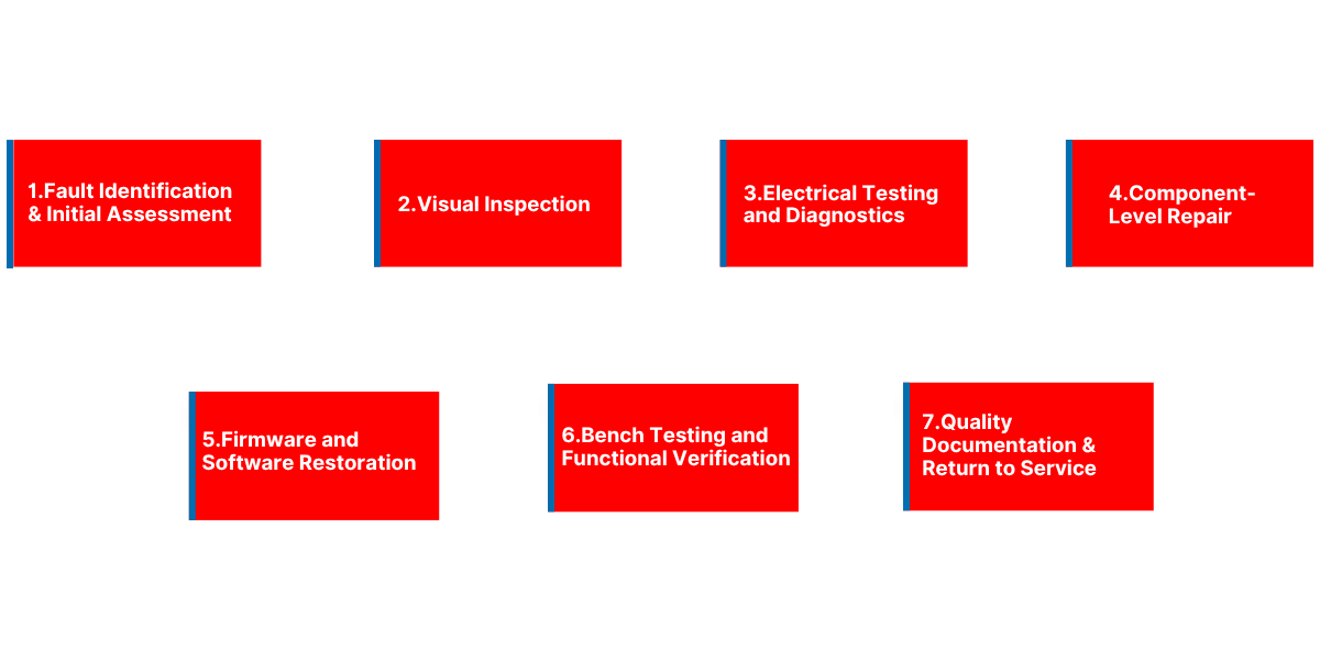
Step 4: Component-Level Repair
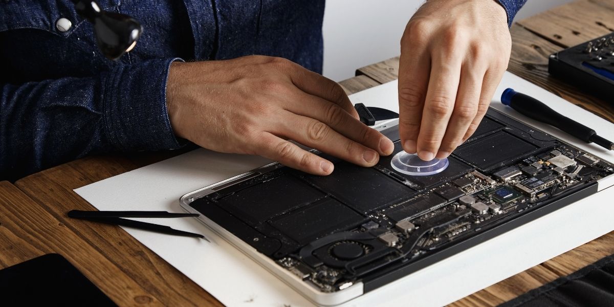
Once the problem is identified, the repair work begins. This stage focuses on fixing the unit at the component level, which requires careful handling, proper tools, and the right replacement parts.
Technicians start by replacing faulty components. Capacitors, which often fail, are removed and replaced with matching ones. Other damaged parts like ICs, display driver chips, and power modules are also replaced. If the original parts are no longer available, suitable alternatives are used to ensure proper performance.
If the display is damaged, it is replaced with care. This includes issues like cracked screens, backlight failure, or the touch not working. The process can be more challenging for older or discontinued models, where parts are harder to find. Physical damages on the board is also repaired.
Burnt PCB tracks are fixed using special repair methods, and corroded connectors are cleaned, repaired, or replaced to restore proper connections. Overall, this approach helps repair the unit instead of replacing it completely, making it a cost-effective solution.
Step 5: Firmware and Software Restoration
Many interface failures are not purely hardware in nature. Firmware corruption, incorrect configuration parameters, and software faults are a significant part of the industrial electronics repair landscape.
After the hardware repairs are completed, the next step is to check the firmware. In industrial electronics repair in Dubai, this step is important to ensure the system runs smoothly after fixing the physical components. If the existing firmware is intact, it is tested to confirm everything is working correctly. If any corruption or errors are found, the firmware is reinstalled using the right tools and software.
Once the firmware is verified, the system configuration is restored. This includes settings like screen layouts, communication parameters, tag mappings, and alarm limits. If backups are available, they are used to restore the data quickly. Otherwise, the settings are manually reconfigured based on documentation.
Step 6: Bench Testing and Functional Verification
Before the repaired unit is sent back for use, it is carefully tested to make sure everything works as expected in real conditions.
The unit is powered on and observed for stability. The display is checked for clear visuals, proper brightness, and accurate colors. The touchscreen is tested across the entire screen to ensure it responds smoothly. All buttons, indicators, and input functions are also checked one by one.
Next, communication is tested to make sure the unit can properly connect and exchange data with other systems. Alarm functions and event logs are also verified to confirm they are working correctly.
In some cases, the unit is left running continuously for 24 to 48 hours. This helps catch any hidden issues that might only appear over time, especially due to heat or continuous use. Only after everything is tested and working perfectly is the unit approved and ready to be used again.
Step 7: Quality Documentation and Return to Service
The final step in the industrial interface repair process is documentation and controlled return to service. A detailed repair report is prepared, covering the original fault description, diagnostic findings, components replaced, firmware actions taken, and test results.
This documentation is important for several reasons. It keeps a clear record of the repair for maintenance tracking, supports warranty claims, and helps future technicians understand what was done if the unit needs service again.
Once everything is complete, the repaired unit is packed carefully to avoid any damage during transport. It is then returned to the client along with all test reports. If needed, on-site support can also be provided to help reinstall the unit. This ensures it is properly connected and works smoothly with the system, including any PLC or network setup.
Reliable Repairs You Can Trust
A proper, step-by-step repair process ensures that the real issue is identified and fixed correctly, not just temporarily covered. In industrial environments, even a small interface failure can lead to downtime or safety risks. Rushing the process or skipping key checks often results in repeated problems and higher costs over time.
At Horizon Elect Devices, every repair is handled with care, precision, and the right technical approach. This ensures faster turnaround, reduced replacement costs, and longer life for your existing equipment. Whether it’s an older HMI that is no longer available or a modern touchscreen system with complex software, a structured repair process delivers consistent and dependable results, helping your operations run smoothly without interruptions.